
Inspection is an important element of quality management because it helps organizations verify whether products, services, processes, and systems meet defined requirements. In the context of Deming quality management, inspection is not viewed simply as a final check for defects. Instead, it forms part of a broader Total Quality Management (TQM) system focused on prevention, continuous improvement, customer satisfaction, and long-term organizational performance.
The Deming Prize, administered by the Japanese Union of Scientists and Engineers (JUSE), is one of the most respected awards associated with TQM. It was established in 1951 in recognition of Dr. W. Edwards Deming’s contribution to statistical quality control and quality management. Organizations are evaluated on how effectively they implement TQM in accordance with their management philosophy, business environment, and organizational needs.
Inspection and audit activities contribute to Deming-based assessment by providing evidence of process control, quality assurance, defect prevention, and improvement. Evaluation can include quality assurance systems, process control, process analysis, quality audits, inspection, measurement, equipment management, supplier control, and customer satisfaction.
Deming assessment does not require every organization to follow an identical quality-management framework. JUSE emphasizes that organizations should develop a TQM system appropriate to their own size, industry, operations, and management environment. Simply copying procedures or creating unnecessary rules for an examination is not the objective.
Ratings therefore focus on the effectiveness and sustainability of quality practices rather than inspection alone. Important considerations include leadership commitment, clear policies and objectives, employee involvement, process improvement, customer orientation, measurable results, and the organization’s ability to maintain improvement over time. The Deming Grand Prize further recognizes organizations that continue applying and improving TQM after receiving the Deming Prize.
In conclusion, Deming certification and ratings provide a comprehensive approach to evaluating organizational quality. Inspection supplies essential evidence about conformity and process performance, while Deming principles ensure that inspection is integrated into prevention, learning, continuous improvement, and overall business excellence.
QA/QC Documentation
Quality Assurance (QA) and Quality Control (QC) documentation is an essential part of any quality management system. It provides a systematic method for planning, implementing, monitoring, recording, and verifying quality requirements throughout a project or organization. Proper documentation ensures that work is performed according to approved standards, specifications, procedures, drawings, and contractual requirements. It also provides objective evidence that quality activities have been completed and that identified problems have been addressed.
Quality Assurance documentation focuses mainly on preventing defects by establishing processes and procedures for achieving the required level of quality. Typical QA documents include the Quality Management Plan, Quality Assurance Plan, method statements, standard operating procedures, inspection and test plans (ITPs), quality procedures, organizational responsibilities, and audit schedules. These documents define how activities should be carried out, who is responsible for them, what standards must be followed, and how compliance will be verified.
Quality Control documentation, on the other hand, focuses on checking and verifying the actual results of work. QC records may include inspection checklists, material inspection reports, test reports, laboratory results, equipment calibration certificates, inspection requests, non-conformance reports (NCRs), corrective action reports, and completed quality records. These documents demonstrate whether materials, workmanship, processes, and finished products meet specified requirements.
One of the most important QA/QC documents is the Inspection and Test Plan (ITP). An ITP identifies the activities requiring inspection or testing, applicable specifications and standards, acceptance criteria, inspection frequency, responsible personnel, and required records. It may also identify hold points and witness points where work cannot proceed without the required inspection or notification.
Document control is another critical aspect of QA/QC management. Documents must be properly identified, numbered, dated, reviewed, approved, distributed, and revised. Only the latest approved versions should be available for use. Obsolete documents should be removed or clearly marked to prevent accidental use. A document register or electronic document management system can help maintain traceability and control.
QA/QC documentation also supports traceability. Materials and activities can be linked to purchase orders, delivery records, batch numbers, test certificates, inspection reports, and final acceptance records. This is particularly important in construction, manufacturing, engineering, and other industries where proving the origin and quality of materials is essential.
When a deviation or defect is identified, an NCR may be issued. The NCR records the nature of the non-conformance, relevant requirement, proposed corrective action, responsible person, and verification of closure. Corrective and preventive actions can then be monitored to prevent recurrence.
Good QA/QC documentation should be accurate, clear, complete, timely, legible, and easily retrievable. Records should be maintained securely for the required retention period and protected from unauthorized alteration or loss. Digital systems can improve efficiency by enabling controlled access, electronic approvals, revision tracking, and rapid retrieval.
In conclusion, QA/QC documentation is more than administrative paperwork. It provides evidence of compliance, supports accountability and traceability, facilitates audits, identifies areas for improvement, and helps organizations consistently achieve required quality standards. A well-controlled documentation system ultimately contributes to improved performance, reduced defects, customer satisfaction, and successful project delivery.
ITP – Inspection & Test Plan
An Inspection and Test Plan (ITP) is a controlled quality document that defines the inspections, tests, verification activities, and acceptance criteria required during the execution of a project. It is commonly used in construction, engineering, manufacturing, infrastructure, and other industries where compliance with approved specifications and standards is essential. The ITP provides a structured approach for ensuring that materials, workmanship, processes, and completed activities meet the specified quality requirements.
The primary purpose of an ITP is to establish what needs to be inspected or tested, when it must be inspected or tested, who is responsible, and what requirements must be satisfied before work can proceed. It helps prevent defects by identifying quality requirements at each stage of an activity rather than relying only on final inspection.
An ITP normally includes the project or activity name, applicable specifications, drawings, codes and standards, inspection stages, testing requirements, acceptance criteria, responsible parties, and required records. It may also identify the inspection authority, such as the contractor, consultant, client, or third-party inspector.
A key feature of an ITP is the classification of inspection points. A Hold Point (H) is a mandatory inspection stage where work cannot continue until the designated authority has completed the required inspection and provided approval or release. A Witness Point (W) allows the designated party to witness an inspection or test, but work may generally proceed according to the agreed procedure if the party does not attend after proper notification. A Review Point (R) indicates that documents, certificates, or records must be reviewed. A Surveillance Point (S) allows periodic monitoring of an activity without requiring a formal release before continuation.
The ITP should be prepared before the relevant work begins and should be based on the contract requirements, approved drawings, technical specifications, applicable standards, method statements, and risk assessments. It should clearly identify the sequence of activities and the quality controls applicable to each stage. For example, in a construction project, an ITP for concrete work may cover material approval, reinforcement inspection, formwork inspection, pre-pour inspection, concrete testing, curing, and final inspection.
Testing requirements should specify the type of test, frequency, applicable standard, equipment, acceptance criteria, and responsible personnel. Test results should be recorded and maintained as part of the project quality records. Any failure to meet acceptance criteria should be documented and managed through the appropriate non-conformance and corrective-action process.
An ITP also supports traceability and documentation control. Inspection requests, checklists, test reports, material certificates, calibration records, and approvals can be linked to specific activities and locations. This creates objective evidence that the required inspections and tests were completed successfully.
In conclusion, an Inspection and Test Plan is a fundamental QA/QC tool for controlling quality throughout a project. It establishes clear inspection responsibilities, prevents uncontrolled progression of work, ensures compliance with technical requirements, and provides reliable quality records. A properly prepared and implemented ITP helps reduce defects, rework, delays, and disputes while supporting safe, efficient, and successful project completion.
MIR – Material Inspection Report
A Material Inspection Report (MIR) is an important Quality Assurance and Quality Control document used to verify that materials delivered to a project comply with approved specifications, drawings, purchase orders, and applicable standards. It provides formal evidence that materials have been inspected and accepted before they are released for use or installation. MIRs are commonly used in construction, engineering, manufacturing, and infrastructure projects.
The main purpose of an MIR is to ensure that only approved and compliant materials are incorporated into the work. Material quality can directly affect the safety, durability, performance, and service life of a completed project. Therefore, materials must be checked carefully before installation. The MIR provides a documented record of this verification process.
An MIR normally contains basic information such as the project name, location, contractor, subcontractor, supplier, MIR number, date of inspection, purchase order number, delivery note number, and material description. It should also identify the relevant specification, drawing, material approval, or technical requirement against which the material is being inspected.
During material inspection, the QC inspector verifies the quantity, type, size, grade, manufacturer, identification marks, batch or heat number, and physical condition of the delivered material. The inspector also checks whether the material is properly packaged, stored, and protected from damage or contamination. Where applicable, certificates such as mill certificates, certificates of conformity, test certificates, warranty documents, and manufacturer data sheets are reviewed.
Material traceability is a major requirement of an MIR system. Materials should be identifiable from the time of delivery through storage, installation, testing, and final completion. Identification numbers, batch numbers, heat numbers, or other markings may be recorded on the MIR to maintain a clear connection between the material and its supporting certificates.
The MIR process generally begins when materials arrive at the project site. The contractor or supplier submits the material for inspection along with the relevant supporting documents. The QC inspector checks the material against the approved requirements. If the material meets all requirements, it may be recommended for acceptance. Depending on the project procedure, the consultant, client, or other authorized representative may then review and approve the MIR.
If the material does not comply with the specified requirements, it should not be used without appropriate disposition. It may be rejected, quarantined, returned to the supplier, or subjected to an approved corrective action. A Non-Conformance Report (NCR) may be raised when required. Any corrective action and subsequent verification should be properly documented.
MIRs also support quality audits and project handover. During an audit, the records demonstrate that materials were inspected before use and that the project maintained compliance with its quality requirements. At project completion, approved MIRs can form part of the final quality dossier or handover documentation.
Effective MIR management requires documents to be accurate, complete, properly numbered, signed or electronically approved, and securely maintained. The records should be easy to retrieve and linked to relevant inspection and testing documentation.
In conclusion, the Material Inspection Report is a critical component of project QA/QC management. It ensures that materials conform to approved requirements before installation, maintains traceability, reduces the risk of defective materials entering the work, and provides documented evidence of quality compliance. A properly implemented MIR process contributes significantly to the overall quality, reliability, safety, and successful completion of a project.
WIR/RFI – Work Inspection Request
A Work Inspection Request (WIR), also commonly referred to as a Request for Inspection (RFI), is an important Quality Assurance and Quality Control document used to formally notify the consultant, client, engineer, or authorized inspector that a particular stage of work is ready for inspection. It ensures that completed work is verified against approved drawings, specifications, method statements, and Inspection and Test Plans (ITPs) before the next stage of work proceeds.
The primary purpose of a WIR/RFI is to establish a formal inspection and approval process. It prevents critical activities from being covered, concealed, or continued without the required inspection. For example, reinforcement, waterproofing, embedded items, underground services, formwork, or electrical installations may require inspection before they become inaccessible.
A typical WIR/RFI contains important project information, including the project name, WIR/RFI number, date of submission, location, discipline, activity description, drawing reference, specification reference, ITP reference, method statement reference, and inspection date and time. It should clearly describe the exact work area and activity being presented for inspection so that the inspecting party can easily identify the work.
Before submitting a WIR/RFI, the contractor’s QC personnel should conduct an internal inspection. The work must be checked for compliance with approved drawings, specifications, approved materials, dimensions, levels, workmanship requirements, and applicable standards. Any identified deficiencies should be corrected before the formal inspection request is submitted.
The WIR/RFI process generally follows a defined sequence. First, the responsible construction team completes the relevant activity. Second, the QC inspector performs an internal inspection and confirms that the work is ready. Third, the WIR/RFI is submitted to the consultant or client with the required supporting documents. These may include approved drawings, checklists, test results, photographs, material approvals, calibration certificates, or previous inspection records.
The inspecting authority then visits the work location and verifies compliance. The inspection result may be recorded as accepted, accepted with comments, rejected, or requiring re-inspection, depending on the project’s procedures. If the work is rejected, the contractor must address the identified deficiencies and submit the work again for inspection. Proper records of the original request, comments, corrective actions, and final approval should be maintained.
WIR/RFIs are particularly important at Hold Points identified in the ITP. At a Hold Point, work should not proceed until the required inspection and release have been completed. Failure to obtain the necessary approval before continuing may result in non-conformance, rework, delays, or contractual disputes.
Effective WIR/RFI management also provides traceability. Each request should have a unique reference number and should be linked to the relevant location, activity, drawing, ITP, and inspection records. Digital systems can improve this process by allowing electronic submissions, approvals, comments, photographs, and status tracking.
In conclusion, the WIR/RFI is a fundamental QA/QC tool for controlling construction and technical activities. It ensures that work is inspected at the appropriate stages, confirms compliance with approved requirements, prevents defects from being concealed, and provides documented evidence of inspection and approval. A well-managed WIR/RFI system improves communication between project stakeholders, reduces rework, supports quality audits, and contributes to successful project completion.
Weld Map & Weld Summary
A Weld Map and Weld Summary are important Quality Assurance and Quality Control documents used to control, identify, inspect, test, and maintain traceability of welded joints in construction, fabrication, piping, structural steel, pressure vessels, and other engineering projects. Together, they provide a clear record of where welds are located, how they were produced, who performed them, and whether they have successfully passed the required inspections and tests.
A Weld Map is a drawing or marked-up document that identifies the location and unique identification number of each weld within a project or fabrication item. Weld numbers are normally assigned sequentially or according to an approved numbering system. The map may identify welds on piping isometrics, structural drawings, equipment drawings, spool drawings, or fabrication drawings. The purpose is to allow every weld to be traced back to its supporting documentation.
The information shown on a Weld Map may include the weld identification number, drawing or spool number, joint location, line or component number, weld type, size, material specification, and inspection requirements. Where applicable, references to the applicable welding procedure specification (WPS), welder qualification, non-destructive testing (NDT), and repair records may also be included.
A Weld Summary is a tabulated record containing detailed information about the welds completed during a project. It generally includes the weld number, date of welding, welder identification, WPS number, material or component details, welding process, joint type, and inspection status. It may also record the required and completed NDT methods, such as Visual Testing (VT), Radiographic Testing (RT), Ultrasonic Testing (UT), Magnetic Particle Testing (MT), or Liquid Penetrant Testing (PT).
One of the most important purposes of weld documentation is welder traceability. Each weld should be linked to the qualified welder who performed it. The welder’s identification number or stamp can then be recorded in the Weld Summary. This allows quality personnel to review welding performance and determine which welds are associated with a particular welder if a defect or repair is identified.
Weld documentation also provides material traceability. Where required, material heat numbers, pipe or plate numbers, and component identification can be recorded and linked to material certificates. This creates a documented connection between the base materials, welding consumables, welding procedure, welder, completed weld, and inspection results.
The Weld Map and Weld Summary are closely connected to NDT and inspection records. Once a weld is completed, the required inspection and testing results are entered against its unique weld number. If a weld passes the specified acceptance criteria, its status can be recorded as accepted. If a defect is detected, the weld may be identified for repair, followed by re-inspection and additional NDT as required. All repair and re-test information should remain traceable to the original weld.
Accurate weld records are also essential for quality audits, project handover, and final documentation. They provide objective evidence that welding activities were carried out using approved procedures and qualified personnel and that required inspections and tests were completed.
In conclusion, the Weld Map and Weld Summary provide a systematic method for controlling welding quality and maintaining complete traceability. By linking each weld to its location, materials, procedure, welder, inspection, NDT results, and repair history, these documents help prevent errors, simplify quality verification, and demonstrate compliance with project requirements. Properly maintained weld records are therefore essential for achieving safe, reliable, and high-quality welded construction.
Welder Qualification Records
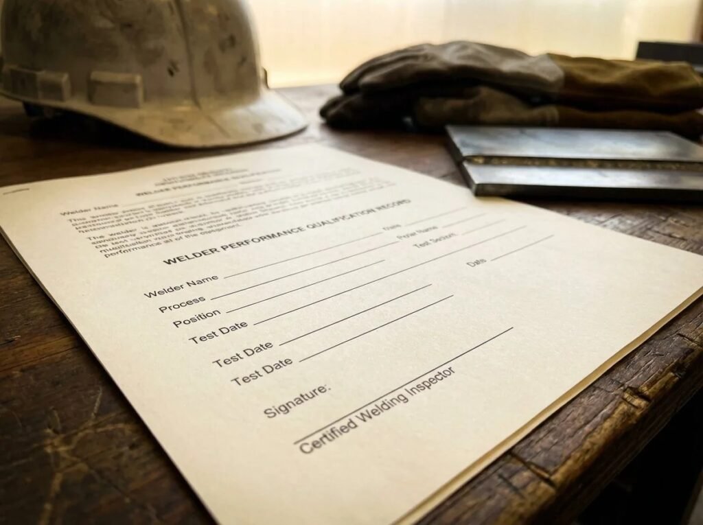
Welder Qualification Records are essential Quality Assurance and Quality Control documents used to demonstrate that a welder has been tested and qualified to perform specific welding activities in accordance with applicable codes, standards, specifications, and approved welding procedures. They provide documented evidence that the individual possesses the required skills and knowledge to produce welds that meet the specified quality requirements.
The main purpose of welder qualification is to ensure that welding is performed only by competent and authorized personnel. Welding quality can directly affect the structural integrity, safety, durability, and service performance of fabricated components. Therefore, projects normally require welders to demonstrate their ability through a qualification test before they are permitted to perform production welding.
A Welder Qualification Record, often called a Welder Qualification Test Record (WQTR) or Welder Performance Qualification (WPQ) record, contains information about the qualification test and the range of welding for which the welder is approved. The exact requirements depend on the applicable welding code and project specification.
Typical information includes the welder’s name, unique identification number, qualification date, welding process, material type, material thickness, pipe diameter where applicable, welding position, joint configuration, filler metal classification, shielding gas, electrical characteristics, and applicable welding procedure specification (WPS). The record also identifies the test standard or code used for qualification.
The qualification process generally begins with a controlled welding test. The welder produces a test coupon under specified conditions. The completed test piece is then subjected to the required visual inspection and, where applicable, destructive or non-destructive testing. Tests may include radiographic testing, ultrasonic testing, bend tests, tensile tests, fracture tests, or other examinations specified by the applicable standard.
If the test results satisfy the required acceptance criteria, the welder is considered qualified within the applicable range. The qualification record should clearly state the essential variables and limitations under which the qualification remains valid. A welder qualified for one process, material range, position, or thickness may not automatically be qualified for every other welding application.
Welder identification and traceability are particularly important during production. Each qualified welder should have a unique identification number or stamp. This identification is recorded against production welds in documents such as the Weld Map, Weld Summary, Weld Inspection Report, and NDT reports. This allows each completed weld to be traced to the person who performed it.
Welder qualification records should also be monitored for continuity or validity requirements. Depending on the applicable code, a welder may need to demonstrate continued use of a particular welding process within a specified period. If the required continuity is not maintained, requalification may be necessary. Records of continuity should therefore be maintained accurately.
QA/QC personnel should verify welder qualifications before assigning welding work. The verification should confirm that the welder’s qualification covers the required process, material, thickness, position, joint type, and other applicable variables. Expired, incomplete, or unsuitable qualifications should not be accepted for production work.
Proper control of Welder Qualification Records also supports audits, inspections, project handover, and regulatory compliance. Records should be securely maintained, properly indexed, and readily retrievable. Any revisions, requalifications, or changes in status should be documented.
In conclusion, Welder Qualification Records provide objective evidence that welding personnel are competent and appropriately qualified for the work assigned to them. By maintaining accurate qualification, continuity, and traceability records, organizations can control welding quality, reduce defects and repairs, demonstrate compliance with applicable requirements, and support the safe and reliable performance of welded structures and equipment.
WPS/PQR/WPQ Records
WPS, PQR, and WPQ records are fundamental welding quality documents used to ensure that welding activities are performed using approved procedures and qualified personnel. They provide a controlled system for demonstrating that the selected welding process can consistently produce sound welds and that welders are competent to carry out the specified work. These records are widely used in construction, structural steelwork, piping, pressure vessels, fabrication, and other engineering projects.
Welding Procedure Specification (WPS)
A Welding Procedure Specification (WPS) is a controlled document that provides instructions for performing a specific welding operation. It defines the essential parameters that the welder must follow during production welding.
A WPS normally includes details such as the welding process, base material specification, material thickness range, joint design, welding position, filler metal classification and size, preheat and interpass temperature, shielding gas, electrical parameters, travel speed, number of passes, post-weld heat treatment, and other applicable requirements.
The WPS ensures consistency between welders and helps prevent welding defects caused by uncontrolled variables. Only approved WPS documents should be used for production welding, and the latest approved revision should be available at the work location.
Procedure Qualification Record (PQR)
A Procedure Qualification Record (PQR) provides documented evidence that a welding procedure has been tested and demonstrated to produce acceptable results. It records the actual variables used during the qualification test rather than simply providing instructions.
The PQR generally identifies the base materials, thickness, joint configuration, welding process, filler metals, welding parameters, preheat and interpass temperatures, shielding gas, welding position, and other variables used during the test. The completed test coupon is subjected to the examinations and tests required by the applicable welding code or specification.
Depending on the application, testing may include visual examination, radiographic or ultrasonic testing, tensile testing, bend testing, macro examination, impact testing, or other specialized tests. The test results are recorded on the PQR. If the results satisfy the applicable acceptance criteria, the procedure can be used as the basis for an approved WPS within the qualified range.
Welder Performance Qualification (WPQ)
A Welder Performance Qualification (WPQ), also known as a welder qualification record, demonstrates that an individual welder has the ability to produce acceptable welds using a specified process and within a defined range of variables.
The WPQ records information such as the welder’s identification, welding process, material type and thickness, pipe diameter where applicable, welding position, filler metal, joint type, test results, and qualification range. The welder must perform a qualification test, and the completed test piece is examined according to the applicable code.
A welder’s qualification is normally limited to the variables and ranges established by the governing code. Therefore, a welder qualified for one welding process, material range, or position may not automatically be qualified for another application.
Relationship Between WPS, PQR, and WPQ
These three documents work together. The PQR qualifies the welding procedure, the WPS provides controlled instructions for production welding, and the WPQ qualifies the individual welder to perform welding within the applicable range.
During QA/QC inspections, personnel should verify that the WPS is approved, supported by an appropriate PQR where required, and applicable to the welding activity. They should also confirm that the welder performing the work has a valid WPQ covering the required process and variables.
In conclusion, WPS/PQR/WPQ records form the foundation of controlled welding quality. Proper preparation, approval, revision control, and traceability of these documents help ensure consistent welding performance, reduce defects and rework, demonstrate code compliance, and provide reliable evidence for inspections, audits, and project handover.
Material Traceability Records
Material Traceability Records are essential Quality Assurance and Quality Control documents used to track and identify materials throughout the complete lifecycle of a project. They provide documented evidence that the materials incorporated into construction or fabrication are the same materials that were inspected, tested, approved, and released for use. Effective traceability is particularly important in construction, piping, structural steel, pressure vessels, mechanical equipment, and other safety-critical applications.
The primary purpose of material traceability is to maintain a clear connection between the material received, its certificates, inspection records, storage location, fabrication activities, installation location, and final completed work. This enables quality personnel to verify compliance with project specifications and applicable standards and to identify the source of materials if a defect or non-conformance is discovered.
Material traceability normally begins when materials are purchased. The purchase order should specify the required material grade, standard, dimensions, certification requirements, and other technical requirements. When materials arrive at the project site, they are inspected against the purchase order and delivery documents. Details such as the material description, manufacturer, quantity, size, grade, batch number, heat number, cast number, serial number, and delivery information may be recorded.
One of the most important traceability documents is the Material Test Certificate (MTC) or certificate of conformity. The certificate provides information about the material’s chemical composition, mechanical properties, manufacturing standard, heat number, and test results, where applicable. The heat or batch number on the certificate should correspond with the identification marked on the physical material.
Material identification must be maintained during storage, cutting, fabrication, welding, and installation. When materials are cut into smaller pieces, the original identification should be transferred to the cut pieces using an approved method. This process is sometimes called material identification transfer or traceability transfer. The objective is to ensure that the identity of the original material is not lost.
In welding and fabrication activities, material traceability may be linked with Weld Maps, Weld Summaries, WPS/PQR records, Welder Qualification Records, inspection reports, and NDT reports. For example, the heat number of a pipe or plate can be linked to a particular spool, weld number, and final installation location. This creates a complete chain of documentation from material receipt to completed work.
Traceability records should also identify the status of materials, such as accepted, rejected, quarantined, or released for construction. Clearly identified storage areas and suitable tagging systems help prevent unauthorized or incorrect materials from being used. Materials that fail inspection or testing should be physically segregated where possible and controlled through the project’s non-conformance process.
Material traceability is particularly valuable when a non-conformance, product failure, or safety concern is identified. The organization can trace the affected material back to its source, supplier, batch, heat, test certificate, fabrication records, and installation location. This supports investigation, corrective action, and, when necessary, targeted replacement rather than unnecessary removal of unaffected materials.
Proper documentation control is essential. Records should be accurate, legible, approved where required, securely stored, and easily retrievable. Digital databases and document management systems can improve traceability by connecting material records with drawings, inspection reports, photographs, certificates, and installation locations.
In conclusion, Material Traceability Records provide a reliable system for controlling material quality from procurement through final installation. They ensure that approved materials are correctly identified and used, support compliance with specifications and standards, simplify inspections and audits, and provide valuable evidence during project handover. A strong traceability system ultimately improves quality, safety, accountability, and long-term reliability of completed work.
Fit-up Inspection Reports
A Fit-up Inspection Report is an important Quality Assurance and Quality Control document used to verify that components are correctly aligned, positioned, prepared, and assembled before welding or permanent joining. It is commonly used in piping, structural steel, pressure vessels, tanks, mechanical fabrication, and other engineering works. The report provides documented evidence that the joint preparation and assembly comply with approved drawings, specifications, welding procedures, and applicable codes.
The main purpose of fit-up inspection is to identify and correct dimensional or assembly problems before welding begins. Once welding is completed, correcting incorrect alignment, excessive gaps, wrong orientation, or incorrect component dimensions can require costly cutting, repair, and rework. Early inspection therefore helps prevent defects, reduce project delays, and maintain production quality.
A Fit-up Inspection Report normally contains basic project information such as the project name, inspection report number, date, location, drawing or spool number, line or component number, joint identification, and applicable specification. It should clearly identify the exact work being inspected and provide sufficient information for future traceability.
During inspection, the QC inspector verifies several important parameters. These may include joint alignment, root gap, bevel angle, root face, internal mismatch or hi-lo, pipe orientation, flange alignment, component dimensions, joint cleanliness, and tack weld quality. The inspector also checks that the correct materials and components have been used and that their identification remains traceable to approved material certificates.
For piping fabrication, particular attention is often given to pipe alignment, flange orientation, flange face condition, bolt-hole orientation, branch connection location, and dimensional tolerances. For structural steel fabrication, inspection may include member alignment, dimensions, joint preparation, connection configuration, temporary attachments, and fit-up of plates or sections.
The inspection should also confirm that the proposed welding activity will be performed using an approved Welding Procedure Specification (WPS) and by a suitably qualified welder. Welding consumables should be appropriate for the approved procedure and properly controlled. Tack welds should be inspected to ensure they are sound and do not introduce defects that could affect the final weld.
A Fit-up Inspection Report may include a checklist with acceptance criteria and actual inspection results. The inspection status can be recorded as accepted, rejected, or requiring correction, depending on the project’s procedures. Photographs may also be attached to provide additional evidence of the inspected condition, particularly for complex assemblies or critical joints.
If deficiencies are identified, they should be corrected before welding proceeds. Examples include excessive root gap, incorrect bevel preparation, poor alignment, wrong component orientation, inadequate cleanliness, or incorrect material identification. After correction, the joint should be re-inspected and the updated status recorded.
Fit-up inspection is closely linked to the Inspection and Test Plan (ITP), Work Inspection Request (WIR/RFI), Weld Map, Weld Summary, WPS, WPQ, material traceability records, and final welding inspection reports. Maintaining these connections provides complete traceability from the material and joint preparation through welding, NDT, and final acceptance.
In conclusion, Fit-up Inspection Reports are essential for controlling the quality of welded and fabricated assemblies. They ensure that components are correctly prepared and positioned before permanent joining, reduce welding defects and rework, and provide documented evidence of compliance with project requirements. Proper fit-up inspection contributes to accurate fabrication, efficient construction, reliable weld quality, and successful project completion.
Visual Inspection Reports
A Visual Inspection Report (VIR) is an important Quality Assurance and Quality Control document used to record the results of visual examination of materials, components, fabrication, welding, installation, and completed work. Visual inspection is one of the most basic and widely used inspection methods because it can identify visible defects, workmanship problems, dimensional issues, surface damage, and other conditions that may affect quality or safety.
The primary purpose of a Visual Inspection Report is to provide documented evidence that the inspected work has been examined and evaluated against specified requirements. Visual inspection is often performed before, during, and after fabrication or installation. It can therefore identify problems at an early stage and prevent defective work from progressing to subsequent activities.
A typical Visual Inspection Report includes information such as the project name, report number, inspection date, location, equipment or component identification, drawing number, specification, inspection stage, inspector’s name, and applicable inspection standard. The report should clearly identify the item or area inspected so that the results can be traced to the relevant work.
For welding activities, visual inspection may be performed before welding, during welding, and after welding. Before welding, the inspector may check joint preparation, cleanliness, alignment, root gap, bevel condition, and fit-up. During welding, inspection may include monitoring preheat, interpass conditions, welding sequence, consumable control, and general workmanship. After welding, the inspector examines the completed weld for visible defects and conformity with the specified acceptance criteria.
Typical visible weld discontinuities that may be identified include cracks, undercut, overlap, excessive reinforcement, surface porosity, arc strikes, poor weld profile, incomplete weld size, spatter, crater defects, and inadequate surface finish. The inspector may also verify weld dimensions, identification markings, and the general condition of the surrounding material.
Visual inspection is not limited to welding. In piping and mechanical work, it can be used to check component condition, flange alignment, supports, surface damage, installation orientation, bolting, cleanliness, coating condition, and general workmanship. In structural steelwork, inspectors may examine member alignment, connection details, weld appearance, bolt installation, surface condition, and dimensional conformity.
The report should compare the observed condition with the approved drawings, specifications, inspection criteria, codes, and applicable procedures. Acceptance criteria should be clearly defined so that inspection decisions are objective and consistent. Measurements or photographs may be included where they provide useful evidence of the inspection results.
If a defect or non-conformance is identified, it should be recorded clearly. Depending on the severity and project procedure, a Non-Conformance Report (NCR) or corrective action may be required. The affected work should be repaired or corrected and then re-inspected. The final status should be documented to demonstrate that the issue has been satisfactorily resolved.
Visual Inspection Reports should be properly controlled and linked with other QA/QC records such as WIR/RFI, Fit-up Inspection Reports, Weld Maps, NDT reports, ITPs, material records, and final inspection documentation. This provides complete traceability throughout the project.
In conclusion, Visual Inspection Reports provide a simple but highly effective method of quality control. They help identify visible defects early, verify workmanship and compliance, support corrective actions, and provide objective evidence for inspections and audits. When performed by competent personnel using approved criteria, visual inspection contributes significantly to the safety, reliability, and overall quality of completed work.
NDT Reports
Non-Destructive Testing (NDT) Reports are important Quality Assurance and Quality Control documents used to record the results of examinations performed on materials, welds, components, and fabricated assemblies without causing damage to the item being tested. NDT is widely used in welding, piping, pressure vessels, structural steel, mechanical equipment, and other critical engineering applications. These reports provide documented evidence that the required examinations have been completed and that the inspected items meet the specified acceptance criteria.
The primary purpose of NDT is to detect surface or internal discontinuities that may not be visible during ordinary visual inspection. NDT methods can identify defects such as cracks, lack of fusion, lack of penetration, internal porosity, inclusions, and other imperfections. The appropriate testing method is selected according to the material, component, weld configuration, applicable code, and project requirements.
Common NDT methods include Visual Testing (VT), Radiographic Testing (RT), Ultrasonic Testing (UT), Magnetic Particle Testing (MT), and Liquid Penetrant Testing (PT). Each method has different capabilities. For example, RT and UT can be used to detect internal discontinuities, while MT and PT are primarily used to identify surface or near-surface defects. The selected method and extent of examination should comply with the approved Inspection and Test Plan, specifications, and applicable standards.
An NDT Report normally contains essential information such as the project name, report number, inspection date, location, component or weld identification, drawing or spool number, material specification, inspection method, testing procedure, equipment identification, calibration information, technician details, and applicable acceptance criteria. The report should clearly identify the exact item examined.
For weld inspection, the report should provide a clear connection to the Weld Map and Weld Summary. Each weld should have a unique identification number so that the NDT result can be traced to the specific joint. The report may also identify the welding process, joint type, weld size, welder identification, and relevant WPS, where required.
NDT personnel should be appropriately qualified and authorized according to the applicable project requirements and standards. Testing equipment must be suitable for the examination and properly maintained or calibrated as required. The NDT procedure should define the testing technique, equipment settings, examination coverage, sensitivity requirements, and evaluation criteria.
After testing, the NDT technician evaluates the indications identified during the examination. The results are compared with the applicable acceptance criteria. The report normally records the result as accepted, rejected, or requiring further evaluation, depending on the project’s procedures. If unacceptable defects are identified, the affected weld or component may require repair followed by additional NDT.
NDT reports are closely connected with other QA/QC documentation, including WIR/RFI, Fit-up Inspection Reports, Visual Inspection Reports, Weld Maps, Weld Summaries, WPS/PQR/WPQ records, material traceability records, and NCRs. Maintaining these links provides complete traceability from material receipt and fabrication through inspection, testing, repair, and final acceptance.
Proper NDT documentation is essential for quality audits, regulatory compliance, project handover, and future maintenance. Reports should be accurate, legible, signed or electronically approved by authorized personnel, and securely stored. Radiographic images, ultrasonic scan data, photographs, or other supporting evidence should be retained where required.
In conclusion, NDT Reports provide objective evidence that critical materials and welds have been examined using appropriate non-destructive methods. They help identify hidden defects, verify compliance with technical requirements, reduce the risk of premature failure, and support safe and reliable construction. Accurate and traceable NDT records are therefore a fundamental part of an effective QA/QC documentation system.
Borescope Inspection Reports
A Borescope Inspection Report is a Quality Assurance and Quality Control document used to record the results of a visual examination performed inside areas that are difficult or impossible to access directly. A borescope, also known as a videoscope or remote visual inspection device, uses a small camera attached to a flexible or rigid probe to inspect internal surfaces, components, welds, tubes, pipes, vessels, machinery, and confined spaces. The inspection can normally be performed without dismantling the equipment, making it a useful non-destructive inspection technique.
The primary purpose of a borescope inspection is to identify and document internal conditions that cannot be adequately examined by conventional visual inspection. It may be used to detect corrosion, cracks, foreign material, surface damage, deposits, blockage, deformation, poor workmanship, weld irregularities, and other conditions that could affect equipment performance or reliability.
A typical Borescope Inspection Report contains essential information such as the project name, report number, inspection date, location, equipment or component identification, inspection area, access point, inspection procedure, equipment details, inspector’s name, and applicable specifications or acceptance criteria. The report should clearly identify the inspected component and the exact area examined.
The inspection equipment should be suitable for the application. Important equipment information may include the borescope or videoscope identification number, probe diameter and length, camera type, lighting system, recording capability, and calibration or functional-check status, where required by the project or applicable procedure. Equipment should be maintained in suitable working condition to ensure reliable inspection results.
During the inspection, the operator guides the probe through an access opening and examines the internal surfaces using the camera and illumination system. Images or video recordings may be captured to provide objective evidence of the observed condition. The inspector should systematically examine the required areas and record any relevant findings.
For piping and pressure equipment, borescope inspection may identify internal corrosion, pitting, deposits, foreign objects, weld conditions, erosion, scaling, or obstructions. In mechanical equipment, it may be used to inspect areas such as engine components, gearboxes, turbines, pumps, heat exchangers, or other enclosed assemblies. In fabrication and construction, it can assist with inspecting inaccessible internal surfaces or confirming cleanliness before closure.
The report should describe observations clearly and objectively. Where defects or irregularities are identified, the report should record their location, approximate size, appearance, orientation, and severity, where these characteristics can be reliably determined. Photographs or video references should be linked to the relevant observation and inspection location.
Acceptance of the inspected condition should be based on approved drawings, specifications, inspection procedures, manufacturer requirements, or applicable codes and standards. A borescope report should not simply state that an item is acceptable without identifying the criteria used for evaluation.
If an unacceptable condition is discovered, appropriate corrective action should be initiated. This may include cleaning, repair, removal of foreign material, additional inspection, or further NDT. After corrective action, a follow-up inspection should be performed and documented.
Borescope reports should be properly controlled and linked to other QA/QC records, such as WIR/RFI, NDT reports, inspection checklists, equipment records, material documentation, and final inspection reports. Digital photographs and videos should be stored securely with appropriate file identification and traceability.
In conclusion, Borescope Inspection Reports provide valuable documented evidence of internal visual examination in areas that are difficult to access. They help identify hidden conditions without unnecessary dismantling, support preventive maintenance and quality verification, and improve inspection traceability. Properly performed and documented borescope inspections contribute to equipment reliability, safety, and overall project quality.
Cleaning/Flushing Records
Cleaning and Flushing Records are important Quality Assurance and Quality Control documents used to verify that piping systems, equipment, vessels, tanks, and other components have been properly cleaned and flushed before commissioning, testing, or placing the system into service. These records provide documented evidence that internal surfaces are free from construction debris, dirt, oil, welding slag, loose scale, foreign materials, and other contaminants that could affect system performance, safety, or reliability.
The primary purpose of cleaning and flushing is to remove unwanted materials from the system before operation. During fabrication and installation, piping and equipment can accumulate welding residues, grinding particles, dust, sand, rust, protective coatings, and other foreign objects. If these contaminants remain inside the system, they may damage pumps, valves, instruments, filters, or other equipment and may restrict flow or contaminate the process.
A Cleaning/Flushing Record normally includes basic project information such as the project name, system or line number, location, record number, date, applicable drawing or isometric number, flushing procedure, responsible personnel, and inspection authority. It should clearly identify the system or section being cleaned so that the activity can be traced to the relevant construction documentation.
Before flushing begins, the system should be prepared according to the approved procedure. This may include confirming that construction activities are complete, removing temporary items where required, installing appropriate temporary connections, protecting sensitive equipment and instruments, and verifying that valves and drains are correctly positioned. The approved method statement or flushing procedure should define the required sequence and acceptance criteria.
Different cleaning methods may be used depending on the system and project requirements. These can include water flushing, air blowing, chemical cleaning, mechanical cleaning, solvent cleaning, or other approved methods. The selected method should be appropriate for the material, service, equipment, and level of cleanliness required.
During flushing, relevant parameters may be recorded. These can include flushing medium, flow rate, pressure, temperature, duration, direction of flow, system identification, and observations of discharged material. Where required, the cleanliness of the discharge may be evaluated through visual examination, screens, filters, sample checks, or other specified criteria.
The inspection team should verify that the required areas have been adequately cleaned and that no unacceptable contamination remains. For critical systems, additional inspections may be required after flushing. The final condition should be documented through inspection records, checklists, photographs, or other supporting evidence where applicable.
If the required cleanliness level is not achieved, the system may need to undergo additional flushing or cleaning. The reason for the failure and the corrective action taken should be recorded. Re-inspection should then be performed before the system is accepted.
Cleaning and flushing records are closely linked to piping inspection records, pressure test reports, line check records, equipment inspection reports, WIR/RFI documentation, punch lists, and commissioning records. Maintaining these links provides complete traceability from fabrication and installation through system preparation and final commissioning.
Proper document control is essential. Records should be accurate, complete, signed or electronically approved by authorized personnel, and securely maintained. The final approved records may become part of the project’s Mechanical Completion and Commissioning Dossier.
In conclusion, Cleaning/Flushing Records provide objective evidence that systems have been properly prepared for testing and operation. They help prevent contamination-related failures, protect equipment, verify compliance with approved procedures, and support safe commissioning. A well-controlled cleaning and flushing documentation system contributes significantly to the reliability, efficiency, safety, and long-term performance of completed systems.
Surface Roughness/Ra Inspection Records
Surface Roughness/Ra Inspection Records are Quality Assurance and Quality Control documents used to measure, verify, and record the surface finish of materials, machined components, weld preparations, coated surfaces, and other manufactured or fabricated items. Surface roughness can significantly affect coating adhesion, sealing performance, fatigue resistance, friction, corrosion protection, and the overall functionality of equipment. Therefore, accurate measurement and documentation of surface roughness are important where specific surface-finish requirements are included in project specifications.
The most commonly referenced parameter is Ra (Arithmetic Average Roughness). Ra represents the average absolute deviation of the measured surface profile from its mean line over a specified evaluation length. It is normally expressed in micrometres (µm) or another specified unit. Other parameters, such as Rz, may also be required depending on the applicable specification or standard.
The primary purpose of a Surface Roughness/Ra Inspection Record is to provide objective evidence that the inspected surface meets the specified roughness requirements. Inspection may be required after machining, grinding, blasting, polishing, preparation for coating, or other surface treatment processes.
A typical inspection record includes the project name, report number, date, location, component identification, drawing or equipment number, inspection area, specified Ra value or range, actual measured values, inspection instrument identification, calibration status, inspector’s name, and acceptance criteria. The report should clearly identify where each measurement was taken.
Before measurement, the surface should be prepared according to the approved inspection procedure. The area should be sufficiently clean and free from loose contamination that could influence the reading. The selected measurement direction and location should be appropriate for the surface and the requirements of the applicable standard.
Surface roughness is commonly measured using a portable surface roughness tester or profilometer. Depending on the instrument, a stylus travels across the surface and records the surface profile. The instrument then calculates the relevant roughness parameter, such as Ra. The equipment should be suitable for the required measurement range and properly calibrated or verified as required by the project’s quality procedures.
During inspection, several readings may be taken from different locations to obtain representative results. The number and location of readings should comply with the approved procedure or specification. For large or irregular surfaces, a defined inspection pattern may be used to ensure adequate coverage.
For surfaces prepared for protective coating, surface roughness is particularly important because the profile can influence coating adhesion and protective performance. Excessively low roughness may provide insufficient mechanical keying, while excessive roughness may result in inadequate coating coverage over surface peaks. Therefore, the specified surface profile should be achieved before coating application.
If measured values do not meet the specified acceptance criteria, corrective action may be required. Depending on the situation, the surface may need additional machining, grinding, blasting, polishing, or other approved treatment. After correction, the area should be re-inspected and the new results recorded.
Surface Roughness/Ra records should be linked with relevant material certificates, fabrication records, coating inspection reports, blasting records, drawings, specifications, and WIR/RFI documentation. This provides traceability between the inspected surface and the final product or equipment.
Proper document control is essential. Inspection records should be accurate, legible, complete, and traceable to the equipment and inspection instrument used. Calibration certificates or instrument verification records should be available where required.
In conclusion, Surface Roughness/Ra Inspection Records provide reliable evidence that surface-finish requirements have been achieved. Accurate measurement helps ensure proper coating performance, machining quality, component functionality, and long-term reliability. Maintaining complete and traceable records also supports inspections, audits, commissioning, and final project handover.
Punch List & Clearance Records
A Punch List and Clearance Record is an important Quality Assurance and Quality Control document used to identify, track, correct, and formally close outstanding items before a project, system, equipment, or work area is considered complete. Punch lists are commonly used during construction, fabrication, commissioning, and project handover. They provide a structured method for ensuring that incomplete work, defects, documentation gaps, and other outstanding requirements are resolved before final acceptance.
The primary purpose of a punch list is to identify deficiencies that remain after the main scope of work has been completed. These items may include incomplete installation, damaged components, incorrect dimensions, missing labels, painting defects, housekeeping issues, outstanding inspections, incomplete testing, or missing documentation. Identifying these items in a controlled record helps prevent them from being overlooked during project completion.
A typical Punch List Record contains information such as the project name, punch list number, date, location, system or equipment identification, description of the outstanding item, drawing or specification reference, responsible contractor or discipline, priority, target completion date, and status. Photographs may also be attached to clearly demonstrate the condition requiring correction.
Punch items are often categorized according to their importance. Critical or high-priority items may affect safety, system functionality, statutory compliance, or the ability to commission the system and therefore require immediate resolution. Lower-priority items may involve minor finishing work, labeling, painting, housekeeping, or documentation corrections. The exact classification system should follow the project’s approved procedures.
Once a punch item is identified, responsibility should be assigned to the appropriate contractor, subcontractor, discipline, or department. The responsible party must complete the required corrective action within the agreed timeframe. Supporting evidence, such as photographs, test reports, inspection records, or revised documents, may be provided to demonstrate completion.
After the corrective action is completed, the item is submitted for verification and clearance. The QC inspector, consultant, client representative, or other authorized person checks the work to confirm that the specified requirement has been satisfied. If acceptable, the punch item is marked as closed or cleared. If the correction is incomplete or unacceptable, the item remains open and may require further action and re-inspection.
Punch List and Clearance Records are closely connected with other QA/QC documents, including WIR/RFI, inspection reports, test certificates, NDT records, commissioning records, NCRs, as-built drawings, and final quality dossiers. This ensures that each outstanding issue can be traced to the original requirement and that its resolution is properly documented.
Effective punch list management requires regular monitoring. A punch list register can be used to track open, submitted for inspection, rejected, and closed items. Periodic reviews or coordination meetings can help identify overdue items and prevent delays to mechanical completion, commissioning, or handover.
Before final project acceptance, the relevant parties should verify that all mandatory punch items have been cleared and that the required supporting documents have been completed. Some minor items may be carried forward under an agreed procedure, but their responsibility, completion date, and status should remain clearly documented.
In conclusion, Punch List and Clearance Records provide an effective system for controlling outstanding work and ensuring that project deficiencies are properly resolved. They improve accountability, support communication between project stakeholders, prevent incomplete work from being overlooked, and provide evidence of final verification. A well-managed punch list system contributes to smooth commissioning, timely handover, and successful project completion.
Final QA/QC Dossier
A Final QA/QC Dossier is a comprehensive collection of quality records compiled at the completion of a project, construction package, fabrication activity, or system. It provides documented evidence that the work has been completed in accordance with approved drawings, specifications, applicable codes, standards, inspection and testing requirements, and contractual obligations. The dossier is commonly submitted to the client, consultant, owner, or authorized representative as part of final acceptance and handover.
The primary purpose of the Final QA/QC Dossier is to provide a complete and traceable history of quality activities performed during the project. It demonstrates that materials were approved, work was inspected, testing was completed, non-conformances were resolved, and final requirements were satisfied. It also provides valuable reference information for future operation, maintenance, modification, and auditing.
The contents of a QA/QC dossier vary depending on the project, contract, discipline, and applicable standards. However, a typical dossier may begin with a cover page, document index, project details, quality plan, approved procedures, inspection and test plans, and relevant specifications. The index should clearly identify each document and its revision or reference number.
Material documentation is an important section of the dossier. It may include Material Inspection Reports (MIRs), Material Test Certificates (MTCs), certificates of conformity, manufacturer certificates, delivery records, material approvals, and material traceability records. These documents demonstrate that the materials incorporated into the completed work were inspected and complied with specified requirements.
For welding and fabrication projects, the dossier may include Weld Maps, Weld Summaries, Welder Qualification Records, WPS, PQR, WPQ records, fit-up inspection reports, visual inspection reports, and NDT reports. These records provide traceability between materials, weld joints, welding procedures, qualified welders, inspection results, repairs, and final acceptance.
Inspection and testing records form another major section. This may include WIR/RFI records, inspection checklists, dimensional inspection reports, pressure or leak test records, electrical or mechanical test results, equipment inspection records, cleaning and flushing records, surface roughness measurements, coating inspection reports, and other project-specific test documentation.
The dossier should also contain records of non-conformances and corrective actions. NCRs, deviation requests, concession approvals, corrective action records, and evidence of closure demonstrate that identified deficiencies were properly evaluated and resolved. Each closed NCR should have sufficient supporting evidence to confirm that the required corrective action was completed and verified.
Punch List and Clearance Records should be included where applicable. These records demonstrate that outstanding work or deficiencies identified during final inspection were addressed and formally cleared. The final dossier should clearly indicate the status of critical punch items and confirm that required completion activities have been verified.
Document control is essential for a reliable QA/QC dossier. All records should be legible, complete, properly identified, approved where required, and arranged in a logical sequence. Only the final approved revisions should be included. Superseded or uncontrolled documents should not be included unless specifically required for historical reference. Electronic dossiers should use appropriate file naming, indexing, access control, and backup procedures.
A well-prepared dossier should also include relevant certificates and approvals, such as equipment calibration certificates, inspection personnel qualifications, laboratory certificates, manufacturer documentation, statutory certificates, and third-party inspection reports where applicable. The exact requirements should be established by the project quality plan and contract.
The dossier preparation process should begin early rather than at project completion. QA/QC personnel should collect and verify records progressively throughout the project. This approach reduces the risk of missing documents, incorrect references, unsigned records, or unresolved discrepancies at handover.
Before submission, the dossier should undergo a final document review. The reviewer should check that required records are present, references are consistent, signatures and approvals are complete, inspection results are acceptable, NCRs are closed, and traceability is maintained. Any missing or incorrect documentation should be corrected before final submission.
In conclusion, the Final QA/QC Dossier is the permanent quality record of a completed project or work package. It demonstrates compliance, provides traceability, supports final acceptance and handover, and preserves essential technical information for future use. A complete, accurate, and well-organized dossier reflects the effectiveness of the project’s quality management system and provides confidence that the completed work meets the required standards and contractual expectations.
NDT & Third-Party Inspection Support
Non-Destructive Testing (NDT) and Third-Party Inspection (TPI) Support are important components of an effective Quality Assurance and Quality Control system. They provide independent verification that materials, fabrication, welding, equipment, and completed work comply with approved drawings, specifications, applicable codes, standards, and contractual requirements. Proper coordination of NDT and third-party inspection activities helps identify defects early, maintain traceability, and provide objective evidence of quality compliance.
NDT support involves coordinating and controlling the examination of welds, materials, components, and equipment without causing damage to the inspected item. Common NDT methods include Visual Testing (VT), Radiographic Testing (RT), Ultrasonic Testing (UT), Magnetic Particle Testing (MT), and Liquid Penetrant Testing (PT). The selected method and inspection extent should be based on the approved Inspection and Test Plan (ITP), project specifications, applicable codes, and approved procedures.
QA/QC personnel are responsible for ensuring that NDT activities are properly planned and performed by qualified and authorized NDT personnel. Before testing begins, relevant documents such as the approved NDT procedure, personnel qualification records, equipment calibration or verification records, and applicable acceptance criteria should be reviewed. The test location and identification of the component or weld should also be clearly established.
NDT results must be properly documented through NDT Reports. Each report should identify the project, component or weld number, inspection method, procedure, examination date, technician, equipment, extent of testing, results, and acceptance criteria. For welding activities, NDT reports should be linked to the Weld Map and Weld Summary so that every test result can be traced to the specific weld.
When unacceptable indications or defects are identified, the affected item should be controlled through the appropriate non-conformance and repair process. Repairs should be performed using approved procedures and then re-examined as required. The original inspection, repair, and re-test results should remain traceable.
Third-Party Inspection provides independent verification by an organization or inspector who is separate from the contractor’s direct production team. TPI activities may include material verification, welding inspection, dimensional inspection, equipment inspection, pressure testing, coating inspection, NDT witnessing, functional testing, and final inspection.
Third-party inspectors may be appointed by the client, owner, consultant, certification body, or another authorized organization. Their involvement should be identified in the project Inspection and Test Plan and coordinated through defined Hold Points, Witness Points, or Review Points. Proper notification should be provided before scheduled inspections so that the third-party inspector can attend when required.
Effective TPI support includes preparing the inspection package before the inspection. This may contain approved drawings, specifications, ITPs, method statements, material certificates, WPS/PQR/WPQ records, previous inspection reports, test procedures, calibration certificates, and relevant checklists. The inspection area should also be ready, accessible, and clearly identified.
All comments, observations, inspection findings, and approvals from the third-party inspector should be recorded and tracked. If an inspection is rejected or conditional approval is issued, corrective actions should be completed and submitted for re-inspection where required.
In conclusion, NDT and Third-Party Inspection Support strengthens the project’s quality control system by providing specialized examination and independent verification. Proper planning, coordination, documentation, and traceability ensure that inspection activities are performed efficiently and that results are accurately recorded. Effective support reduces quality risks, prevents costly rework, facilitates client acceptance, and contributes to the safe and reliable completion of the project.
Coordinate NDT Activities As Per Approved ITP/Project Requirements
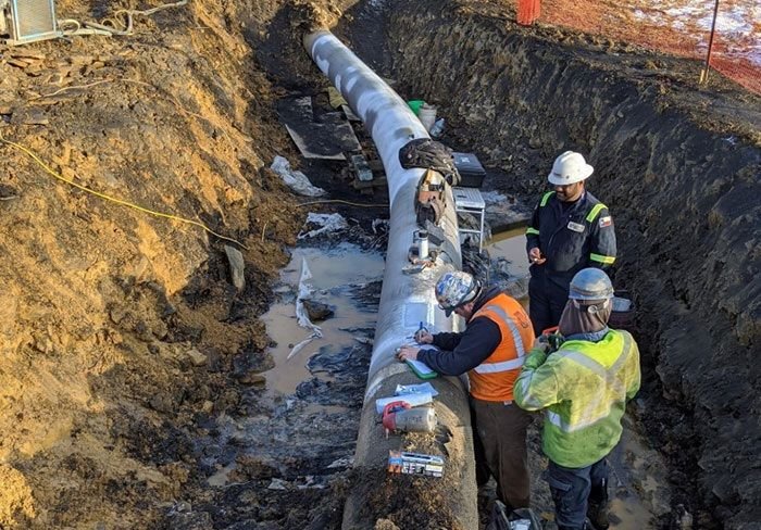
Non-Destructive Testing (NDT) is a critical quality-control activity used to verify the integrity of welds, materials, components, and fabricated assemblies without causing damage to the inspected item. Proper coordination of NDT activities is essential to ensure that examinations are performed at the correct stage, using approved procedures, qualified personnel, suitable equipment, and project-specific acceptance criteria. NDT activities must always be coordinated in accordance with the approved Inspection and Test Plan (ITP), project specifications, drawings, applicable codes, and contractual requirements.
The coordination process should begin with a detailed review of the approved ITP and project requirements. The QA/QC team should identify all activities requiring NDT, the applicable inspection methods, required percentage or extent of examination, acceptance criteria, Hold Points, Witness Points, and responsible parties. Common NDT methods include Visual Testing (VT), Radiographic Testing (RT), Ultrasonic Testing (UT), Magnetic Particle Testing (MT), and Liquid Penetrant Testing (PT).
Before arranging the inspection, the QA/QC coordinator should confirm that the work is ready for examination. Welding should be completed and visually inspected where required, weld identification should be clearly marked, and relevant materials and welding records should be traceable. Supporting documents such as the Weld Map, Weld Summary, WPS, WPQ, Fit-up Inspection Report, Visual Inspection Report, and material records should be available.
The NDT contractor or inspection personnel should be appropriately qualified and authorized in accordance with the applicable project requirements and standards. Their qualifications should be verified before assignment. NDT equipment must also be suitable for the examination method and maintained or calibrated as required. The approved NDT procedure should be reviewed to confirm that the proposed technique complies with the project requirements.
Proper scheduling and communication are important parts of NDT coordination. The QA/QC team should coordinate with construction, welding, NDT personnel, consultants, clients, and third-party inspectors to establish suitable inspection dates and locations. Where the ITP identifies a Witness or Hold Point, the required parties should receive formal notification within the specified time. NDT should not proceed in a manner that bypasses mandatory inspection or approval requirements.
During the examination, the QA/QC representative should ensure that the correct component, weld number, location, and inspection extent are being examined. Any required safety controls should also be established, particularly for methods such as radiography that may involve controlled areas and specialized safety requirements. NDT activities should be performed in accordance with approved procedures and applicable safety regulations.
After testing, the NDT results should be reviewed against the specified acceptance criteria. The inspection report should contain sufficient information to identify the item tested, method used, procedure reference, technician, equipment, inspection extent, results, and final acceptance status. Where applicable, radiographic images, ultrasonic data, photographs, or other supporting records should be retained.
If unacceptable indications are identified, the affected weld or component should be controlled through the project’s Non-Conformance Report (NCR) or repair process. The defect should be evaluated, repaired using an approved procedure, and re-examined as required. The original inspection result, repair details, and re-test results should remain linked to the same weld or component identification.
Traceability is a key requirement throughout the process. Each NDT result should be connected to the relevant Weld Map, Weld Summary, WPS/PQR/WPQ records, material certificates, inspection requests, and final QA/QC dossier. This ensures that the complete history of each inspected weld or component can be demonstrated during audits and final handover.
In conclusion, effective coordination of NDT activities requires careful planning, document verification, personnel qualification checks, scheduling, inspection control, result evaluation, and record management. By following the approved ITP and project requirements, QA/QC personnel can ensure that NDT is performed at the correct stages and that all results are accurately documented. Proper coordination reduces the risk of undetected defects, prevents delays and rework, supports client and third-party acceptance, and contributes to the safety, reliability, and successful completion of the project.
Coordinate With TPI/Client Inspectors For Inspection and Witness Points
Coordination with Third-Party Inspection (TPI) and Client Inspectors is an essential part of Quality Assurance and Quality Control management. Effective coordination ensures that inspections, tests, Hold Points, Witness Points, and Review Points identified in the approved Inspection and Test Plan (ITP) are completed in accordance with project requirements. Proper communication and planning help prevent delays, rejected work, missed inspections, and disputes during construction, fabrication, and commissioning.
The coordination process begins with a detailed review of the approved ITP, project specifications, drawings, method statements, and contractual requirements. QA/QC personnel should identify all activities requiring client or TPI involvement and understand whether each activity is classified as a Hold Point, Witness Point, Review Point, or surveillance activity. The responsible parties and notification requirements should also be clearly established.
A Hold Point is a mandatory inspection stage where work cannot proceed until the designated inspector has completed the required inspection and released the activity. A Witness Point allows the client or TPI inspector to witness a specific activity or test. The approved project procedure determines whether the work may proceed if the inspector does not attend after proper notification. Review Points generally require documents or records to be reviewed, while surveillance allows inspectors to monitor work periodically.
Before requesting an inspection, the contractor’s QA/QC team should conduct an internal inspection. The work should be complete and ready for presentation, and all relevant requirements should have been verified. Supporting documents such as approved drawings, specifications, checklists, material certificates, WPS/PQR/WPQ records, calibration certificates, test procedures, previous inspection reports, and NDT records should be available as applicable.
A formal Inspection Notification or WIR/RFI should be submitted according to the project’s approved communication procedure. The notification should clearly state the project, location, activity, inspection date and time, drawing or specification reference, ITP reference, and inspection type. Adequate advance notice should be provided to allow the client or TPI inspector to arrange attendance.
On the scheduled inspection date, the QA/QC representative should ensure that the inspection area is accessible, safe, properly identified, and ready for examination. Required personnel, equipment, measuring instruments, test certificates, and inspection documents should be available. The QA/QC representative should accompany the inspector and provide accurate technical information without interfering with the independent inspection process.
During the inspection or witness activity, any comments, observations, measurements, test results, or instructions should be recorded accurately. If the inspector identifies a deficiency, the issue should be communicated to the responsible construction team and corrected in accordance with the approved procedure. Where necessary, an NCR or corrective action record should be raised.
If an inspection is rejected, the reason should be clearly documented. The contractor should complete the required corrective action and arrange a re-inspection through the formal notification process. No activity subject to a mandatory Hold Point should proceed without the required release or documented authorization.
Good coordination also requires continuous communication. Inspection schedules should be updated regularly, and changes to planned activities should be communicated promptly to the client and TPI representatives. Last-minute changes, incomplete inspection areas, or repeated cancellations should be avoided because they can affect project progress and stakeholder confidence.
All inspection outcomes should be incorporated into the project quality records. Approved WIR/RFIs, inspection checklists, TPI reports, client comments, release notes, test reports, photographs, and corrective action records should be properly indexed and maintained for the Final QA/QC Dossier.
In conclusion, effective coordination with TPI and Client Inspectors ensures that required inspection and witness activities are performed at the correct stages and in accordance with the approved ITP. Proper preparation, timely notification, clear communication, accurate documentation, and prompt corrective action help maintain quality, avoid delays, and build confidence among project stakeholders. A disciplined inspection coordination process ultimately supports successful project completion, commissioning, and final handover.
Review NDT Reports and Acceptance Criteria
Reviewing Non-Destructive Testing (NDT) Reports and Acceptance Criteria is a critical Quality Assurance and Quality Control activity. The purpose of the review is to confirm that NDT examinations have been performed correctly, the reported results are complete and traceable, and the inspected welds or components meet the requirements of the approved project specifications, applicable codes, standards, and Inspection and Test Plan (ITP). A proper review helps prevent defective work from being accepted and ensures that quality records provide reliable evidence of compliance.
The review should begin by confirming that the NDT report is associated with the correct project, component, weld, location, and inspection request. Weld identification numbers should correspond with the Weld Map and Weld Summary. Other relevant references, such as drawing numbers, spool numbers, line numbers, equipment numbers, and inspection locations, should also be checked. Correct identification is essential because an accurate test result is of little value if it cannot be linked to the correct item.
The next step is to verify that the specified NDT method and extent of examination have been followed. Depending on the project requirements, the examination may involve Visual Testing (VT), Radiographic Testing (RT), Ultrasonic Testing (UT), Magnetic Particle Testing (MT), Liquid Penetrant Testing (PT), or another approved method. The report should clearly identify the method, applicable procedure, examination extent, and relevant standard.
The qualifications of NDT personnel should also be verified where required. The technician or examiner should hold the appropriate qualification and authorization for the method performed. The NDT equipment should be suitable for the examination, and required calibration or verification records should be available and valid at the time of inspection.
A key part of the review is checking the acceptance criteria. Acceptance criteria define the limits used to determine whether an indication or discontinuity is acceptable. They may be established by the project specification, applicable welding or inspection code, engineering standard, approved procedure, or contractual requirement. QA/QC personnel should ensure that the correct revision and applicable acceptance criteria have been used rather than relying on assumptions or general industry practice.
For Radiographic Testing, the review may include examination identification, coverage, image quality, sensitivity, density where applicable, location markers, and evaluation of reported indications. For Ultrasonic Testing, relevant information may include examination coverage, equipment settings, calibration, scanning technique, indication evaluation, and reported results. For MT and PT, the review may consider surface preparation, test coverage, application method, examination conditions, and evaluation of relevant indications.
The report should clearly state the final result, such as accepted or rejected, and should identify any relevant indications. If a discontinuity exceeds the applicable acceptance criteria, the item should not be accepted without an approved disposition. It may require repair, additional examination, engineering evaluation, or other corrective action in accordance with the project procedure.
When defects are identified, the original NDT report should remain part of the quality record. Repair details and subsequent re-examination results should be linked to the original weld or component identification. This ensures complete traceability of the original inspection, defect, repair, and final acceptance.
The reviewer should also check the report for completeness, including dates, signatures or electronic approvals, procedure references, technician details, equipment identification, results, acceptance criteria, and supporting attachments. Missing information should be corrected before the report is included in the final QA/QC dossier.
In conclusion, reviewing NDT reports requires more than checking whether a report states “accepted.” The QA/QC reviewer must verify identification, inspection method, extent, personnel qualification, equipment status, applicable acceptance criteria, results, and traceability. A systematic review ensures that NDT records accurately demonstrate the integrity and compliance of inspected work. Proper review ultimately reduces quality risks, prevents premature acceptance of defective items, supports audits and client approval, and contributes to the safe and reliable completion of the project.
Maintain Weld Rejection, Repair and Re-Inspection Records
Weld Rejection, Repair, and Re-Inspection Records are essential Quality Assurance and Quality Control documents used to control welding defects from initial identification through final acceptance. These records provide a complete history of rejected welds, corrective actions, repairs, and subsequent inspections. Proper maintenance of these records ensures traceability, prevents defective welds from being overlooked, and demonstrates compliance with approved welding procedures, project specifications, applicable codes, and inspection requirements.
A weld may be rejected following Visual Testing (VT), Radiographic Testing (RT), Ultrasonic Testing (UT), Magnetic Particle Testing (MT), Liquid Penetrant Testing (PT), dimensional inspection, or other required examinations. When a defect is identified, the affected weld must be clearly identified using its unique weld number, location, drawing or spool reference, and relevant material information. The rejection should be recorded in the appropriate inspection report, weld summary, NCR, repair record, or project quality database.
The first step in managing a rejected weld is to verify and document the reason for rejection. The reported defect may include lack of fusion, lack of penetration, cracks, porosity, undercut, slag inclusion, excessive reinforcement, unacceptable weld profile, or another condition exceeding the specified acceptance criteria. The rejection record should identify the applicable acceptance requirement and provide sufficient information to understand the nature and location of the defect.
After rejection, the weld should be controlled so that it is not accidentally accepted or concealed. Its status should be clearly identified as rejected, under repair, or awaiting re-inspection. Where required, an NCR should be raised in accordance with the project’s quality procedure. The responsible welding or construction team should then determine the appropriate corrective action.
Repairs must be carried out using an approved repair procedure or welding procedure. The repair process may include removal of defective material by grinding, machining, or other approved methods, followed by re-welding. The repair should be performed by a welder who is appropriately qualified for the applicable welding process and material range. Relevant preheat, interpass temperature, consumable control, and other WPS requirements should be maintained during the repair.
All repair activities should be documented. The repair record may include the weld number, defect type, defect location, repair method, repair date, welder identification, applicable WPS, number of repair attempts, and relevant observations. Where necessary, photographs or sketches may be included to identify the repaired area.
Following completion of the repair, the weld must undergo re-inspection and re-testing as required by the applicable code, specification, or project procedure. The same or an additional NDT method may be used depending on the nature of the defect and repair. The new inspection result should be linked to the original rejection record so that the complete history remains traceable.
If the repaired weld passes the required acceptance criteria, its status can be changed to accepted or cleared. If it fails again, further corrective action and re-inspection may be required. Repeated repairs should be carefully monitored because excessive repair can affect weld integrity or indicate problems with welding procedures, materials, equipment, or welder performance.
QA/QC personnel should maintain a Weld Rejection and Repair Register to monitor rejected welds, repair status, re-inspection dates, and final disposition. The register can also provide useful information for identifying trends, such as repeated defects associated with a particular welder, welding procedure, material, or work area.
These records should be connected with the Weld Map, Weld Summary, WPS/PQR/WPQ records, NDT Reports, Visual Inspection Reports, WIR/RFI records, NCRs, and Final QA/QC Dossier. This provides a complete quality trail from the original weld through rejection, repair, re-testing, and final acceptance.
In conclusion, accurate management of weld rejection, repair, and re-inspection records is essential for welding quality control. A systematic process ensures that rejected welds are properly identified, repaired using approved methods, independently re-inspected, and formally cleared. Complete records improve traceability, support audits and client inspections, identify recurring quality problems, and provide objective evidence that the final welded product meets the required quality and safety standards.
Maintain Weld/NDT Inspection Status and Tracking
Weld/NDT Inspection Status and Tracking is an essential Quality Assurance and Quality Control activity used to monitor the progress and acceptance status of welded joints and their associated Non-Destructive Testing (NDT) activities. A well-maintained tracking system provides clear visibility of completed, pending, rejected, repaired, and accepted welds. It also ensures that no weld is accidentally released, concealed, or included in final documentation without completing the required inspections and tests.
The primary purpose of weld and NDT tracking is to maintain complete traceability from welding through final acceptance. Each weld should have a unique identification number that can be linked to the Weld Map, Weld Summary, material records, welding procedure, welder identification, inspection reports, NDT reports, repair records, and final quality dossier.
The tracking process should begin when a weld is planned or identified on the approved drawing, isometric, fabrication sketch, or Weld Map. Relevant information such as the weld number, drawing or spool number, line or component number, material details, joint type, welding process, WPS reference, and welder identification should be entered into the weld tracking register or approved electronic system.
As welding progresses, the status of each weld should be updated. Typical statuses may include Fit-up Pending, Fit-up Accepted, Welding Completed, Visual Inspection Pending, Visual Accepted, NDT Pending, NDT Accepted, Rejected, Under Repair, Re-Test Pending, Re-Test Accepted, and Final Accepted. The exact status terminology should follow the project’s approved procedures.
After welding is completed, the weld should undergo the required visual inspection. If the visual inspection is satisfactory, the weld can proceed to the applicable NDT stage. The tracking system should record the relevant inspection report number, date, inspector, and result. If NDT is required, the appropriate method and examination percentage should also be recorded.
NDT tracking should clearly identify the NDT method, report number, examination date, technician, result, and acceptance status. For example, a weld may require RT, UT, MT, or PT according to the approved ITP and project specification. The tracking register should show whether the required examination has been completed and whether the result is acceptable.
If an NDT examination identifies an unacceptable defect, the weld status should immediately be changed to rejected or under repair. The defect should be linked to the relevant rejection, NCR, or repair record. After repair, the required re-inspection should be scheduled and the new NDT result entered into the tracking system. The original rejection should remain visible so that the complete history is preserved.
Regular review of the weld/NDT register is important. QA/QC personnel should compare the tracking register with Weld Maps, WIR/RFI records, NDT reports, fabrication progress, and inspection records to identify missing or inconsistent information. Any discrepancy should be investigated and corrected before final acceptance.
A useful tracking system can also generate progress information, such as the total number of welds completed, percentage inspected, percentage accepted, number of rejected welds, repair rate, and outstanding NDT examinations. This information helps project management identify potential delays and recurring quality problems.
Before mechanical completion or final handover, the tracking register should be reconciled against the final project documentation. Every weld should have the required inspection and NDT records, and all rejected or repaired welds should have documented final acceptance. Outstanding items should be addressed before the relevant system is released, subject to the approved project procedure.
In conclusion, maintaining accurate Weld/NDT Inspection Status and Tracking provides an effective control mechanism for welding quality. It ensures that every weld is accounted for, required examinations are completed, defects are properly controlled, and final acceptance is supported by complete records. A disciplined tracking system improves communication, prevents missed inspections, supports audits and client reviews, and provides reliable evidence for the Final QA/QC Dossier and project handover.
Take the Next Step Today
Don’t wait to enhance your business’s quality and efficiency. Partner with Deming Certification & Ratings Pvt Ltd. and experience the transformation that comes with expert consultancy and training. Contact us today to learn more about how we can help you achieve your business goals. Reach out via phone at +91-9322728183, visit our website at www.demingworld.in, or email us at info@demingworld.in Let us be your guide on the journey to excellence and innovation.